Location: Home >> Detail
J Sustain Res. 2026;8(3):e260066. https://doi.org/10.20900/jsr20260066
 ,
João Garcia 1,2,3,*
,
João Garcia 1,2,3,*
1
2
3
*
Refrigeration plays a crucial role worldwide, without which food safety would be compromised. However, with increasing environmental challenges, sustainability concerns, and new regulations, traditional systems that use fluids with a high global warming potential (GWP) and impact on the ozone layer (ODP) are becoming increasingly obsolete. In this context, the use of refrigerants that do not present these problems, such as ammonia and carbon dioxide, may appear as a more sustainable and efficient solution. This work aimed to develop a proposal for optimising an existing refrigeration installation by switching from fluorinated refrigerants, R404A, to natural refrigerants, specifically carbon dioxide (R744) and ammonia (R717), with the aim of improving energy efficiency, enhancing sustainability, and reducing environmental impacts. The optimisation proposal consisted of centralising the refrigeration systems, which were previously independent, and including them in the cascade system, with R744 at low pressure and R717 at high pressure, using the positive points of each fluid to try to maximise energy performance. The installation was dimensioned with the new natural refrigerants. The results show significant gains: the electrical power absorbed was reduced by 35.2%, while the COP increased from 2.11 to 3.26, corresponding to an improvement of 54.4%. In environmental terms, there was a 39.5% reduction in annual CO2 emissions and a 40.5% decrease in the TEWI Index, corresponding to 4.3 million kgCO2 less over the lifetime of the installation. In economic terms, annual electricity costs fell by around 39.6%, resulting in savings over the lifetime of the installation of more than €370,000. This study reinforces the technical, environmental, and sustainability benefits of transitioning to natural refrigerants in industrial refrigeration installations.
The main objective of this study is to analyse and develop an optimisation proposal for an existing industrial refrigeration system by replacing the current refrigerant, R404A, with natural refrigerants, namely carbon dioxide (CO2) and ammonia (NH3), recognized for their high energy efficiency and low environmental impact [1]. The proposal also includes the centralisation of currently independent systems, such as freezing tunnels and cold storage chambers, into a single cascade installation, aiming to improve energy performance and reduce environmental impact [2]. To achieve this objective, the refrigeration system was redesigned and optimised based on an existing facility in Portugal. This process involved the selection and specification of equipment compatible with the thermodynamic properties and physicochemical characteristics of CO2 and NH3, taking into account important differences compared to the original system. Key components analysed include compressors, condensers, evaporators, expansion valves, and specific safety devices, which are essential to ensure safe operation given the toxicity and flammability potential [3]. A comparative analysis was also performed between the current and the proposed optimised system, considering energy, environmental, and economic indicators [4]. This evaluation enables quantification of performance gains, reduction in energy consumption, and the technical and economic feasibility of transitioning to the new natural refrigerants [5]. Despite the growing interest in natural refrigerants and cascade refrigeration systems, there is still a lack of detailed case studies evaluating the combined energy, environmental, and operational cost benefits of converting existing industrial refrigeration installations from fluorinated refrigerants to natural refrigerant technologies under real operating conditions. In particular, limited information is available regarding the overall impact of simultaneously implementing refrigerant substitution, system centralization, and cascade system integration in industrial food-processing facilities.
To address this research gap, this study aims to evaluate the technical, environmental, and economic performance of an industrial refrigeration installation in Portugal after its conversion from an R404A-based configuration to a centralized NH3/CO2 cascade system.
The study is guided by the following research questions:
RQ1.
RQ2.
RQ3.
The remainder of this paper is organized as follows. Section “Literature Review” presents the literature review. Section “Materials and Methods” describes the materials and methods adopted in the study, including the characteristics of the original and optimized systems and the calculation procedures. Section “Results” presents and discusses the results obtained from the energy, environmental, and operational cost assessments. Finally, Section “Conclusions” summarizes the main conclusions and identifies directions for future research.
Refrigeration is essential in the food industry, ensuring product preservation, safety, and quality throughout the supply chain [6]. Traditional systems relying on fluorinated refrigerants contribute significantly to global warming and ozone depletion due to their high GWP and ODP [7]. With stricter environmental regulations, such as the EU F-gas Regulation [8], sustainable alternatives are increasingly required [9]. Natural refrigerants, notably carbon dioxide (CO2, R744) and ammonia (NH3, R717), offer high energy efficiency and minimal environmental impact [10]. CO2 provides excellent thermodynamic performance at low temperatures [11], while NH3 is highly efficient at higher temperatures [12,13]. However, their adoption presents technical challenges, including high operating pressures for CO2 and toxicity and flammability concerns for NH3, making system design and safety critical considerations [14,15]. Efficient refrigeration is crucial not only for operational performance [16] but also for food safety, minimizing microbial growth, reducing spoilage, and extending product shelf life [17]. By demonstrating the benefits of natural refrigerants in industrial applications, this study contributes to the broader adoption of sustainable and energy-efficient refrigeration practices. Refrigerants are the working fluids in refrigeration systems, responsible for absorbing heat from the cooled space through evaporation, thereby producing the desired cooling effect [18]. Over time, their development has been driven by safety, stability, economic considerations [19], and environmental concerns, leading to continuous improvements in efficiency and operational reliability [20]. Selecting an appropriate refrigerant for a vapour-compression cycle is a process that requires evaluating multiple parameters, including thermodynamic properties, operating temperature ranges, pressure-temperature relationships, compression process requirements, material and lubricant compatibility, toxicity and flammability, and environmental indicators such as Ozone Depletion Potential (ODP) and Global Warming Potential (GWP) [21]. Since no single refrigerant satisfies all criteria perfectly, a careful analysis is required to determine the most suitable solution for a specific application. Many commonly used refrigerants are synthetic chemicals designed for specific performance requirements; however, they often present significant environmental impacts due to high ODP or GWP [22]. GWP measures the heat retention capacity of a gas relative to CO2, while ODP quantifies its effect on ozone layer depletion. Refrigerants can be broadly classified as non-natural—such as chlorofluorocarbons (CFCs), hydrochlorofluorocarbons (HCFCs), and hydrofluorocarbons (HFCs)—which have high environmental impact, or natural, such as CO2 and NH3, which have negligible ODP and low GWP. Safety classifications include toxicity classes A (low) and B (high), and flammability classes 1–3. The EU F-Gas Regulation [8] enforces the phased reduction of fluorinated greenhouse gases, limiting market availability and GWP in new equipment, thereby promoting environmentally responsible refrigeration technologies. CO2 has regained interest as a refrigerant due to its negligible ODP and low GWP [7]. CO2 offers several thermodynamic advantages, including high heat transfer coefficients, significant energy content, low sensitivity to pressure drops, and very low liquid viscosity [7]. However, because CO2 is colourless and odourless, refrigerant leaks cannot be readily detected by human senses. Consequently, dedicated gas detection and monitoring systems are required to ensure safe operation. Ammonia is a fully natural refrigerant with ODP = 0, GWP = 0, and biodegradable properties. It has been used in industrial refrigeration since the mid-19th century and is characterised by high thermodynamic efficiency, high cooling capacity, and low cost compared to synthetic alternatives. Its distinct odour facilitates leak detection, enhancing safety. Due to its toxicity and flammability, NH3 is mainly used in industrial installations, often in auxiliary circuits to minimize direct contact with stored products, ensuring both operational safety and product integrity. Unlike previous studies that primarily focus on isolated refrigeration component improvements or solely on refrigerant replacement strategies, the present work proposes an integrated optimisation methodology for industrial refrigeration systems. The novelty of this study lies in the simultaneous implementation of a low-GWP NH3/CO2 cascade refrigeration architecture, the centralisation of independent refrigeration subsystems, and the combined thermodynamic, environmental, and economic assessment of the optimised installation. In addition to improving the system COP and reducing annual energy consumption, the proposed approach significantly decreases CO2 emissions while ensuring compliance with current environmental regulations regarding fluorinated refrigerants. Therefore, this work contributes not only as an engineering retrofit case study, but also as a comprehensive framework for sustainable industrial refrigeration system optimisation.
This study proposes the optimisation of an existing industrial refrigeration plant in Portugal by transitioning from R404A to a cascade system using CO2 at low temperatures and NH3 at high temperatures. The approach also integrates previously independent subsystems, such as freezing tunnels and cold storage chambers, into a centralised configuration. The aim is to maximize energy efficiency, reduce environmental impact, and ensure technical and economic feasibility. This section presents the case study analysed, which corresponds to a company located in Portugal that produces and distributes meals for schools and universities. The refrigeration plant serves a variety of industrial processes, including frozen and chilled food preservation, food pasteurisation, which covers both rapid heating and immediate cooling. It also includes an ice bank that supplies chilled water, essential both for cooling the pasteurised product and for air-conditioning the building. The facility consists of 18 refrigeration chambers, 6 frozen food chambers and 6 freezing tunnels, each space designed for a specific purpose and with refrigeration capacity adjusted to the respective needs. The analyses of the original and optimized refrigeration systems were carried out through thermodynamic and engineering calculations developed by the authors using Microsoft Excel spreadsheets. The calculations were based on refrigeration cycle equations, energy balance principles, operating conditions of the installation, and manufacturers’ technical data for the main equipment components. The developed calculation procedure was used to evaluate system performance, energy consumption, environmental impact, and economic indicators. Table 1 summarises the refrigeration capacities of the original installation (scenario 1).
The layout of the installation showing the arrangement of all the spaces, and the distribution of the pipework throughout the installation. Due to its large size, the installation layout was divided into two parts, as shown in Figure 1 (Installation layout, Part 1/2) and Figure 2 (Installation layout, Part 2/2). Figure 2 represents the horizontal continuation of Figure 1.
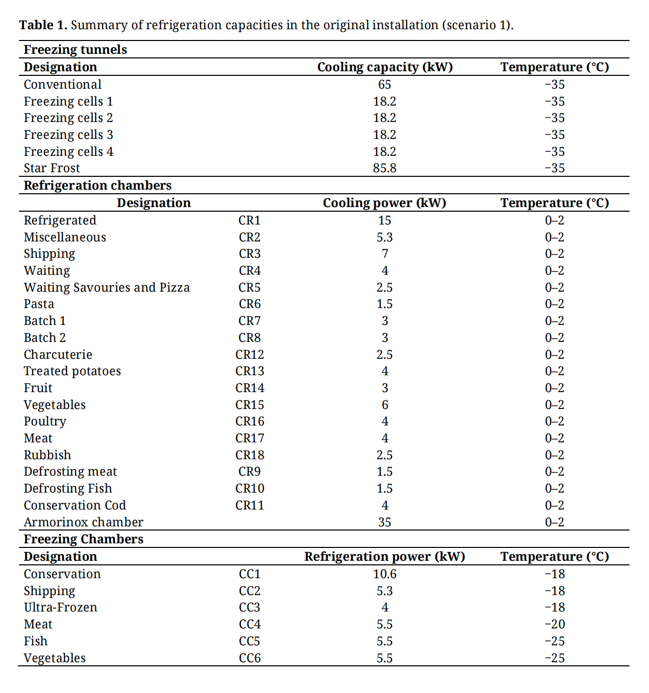 Table 1. Summary of refrigeration capacities in the original installation (scenario 1).
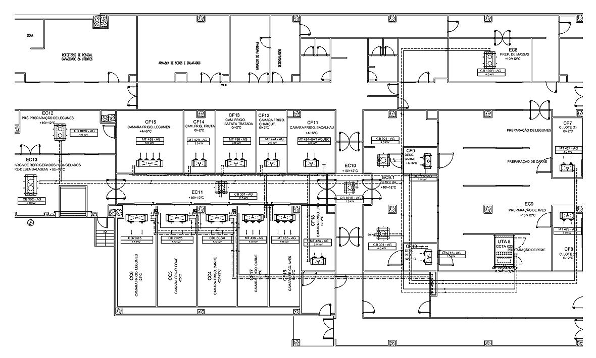 Figure 1. Installation layout (1/2). (Source: Dimensionar).
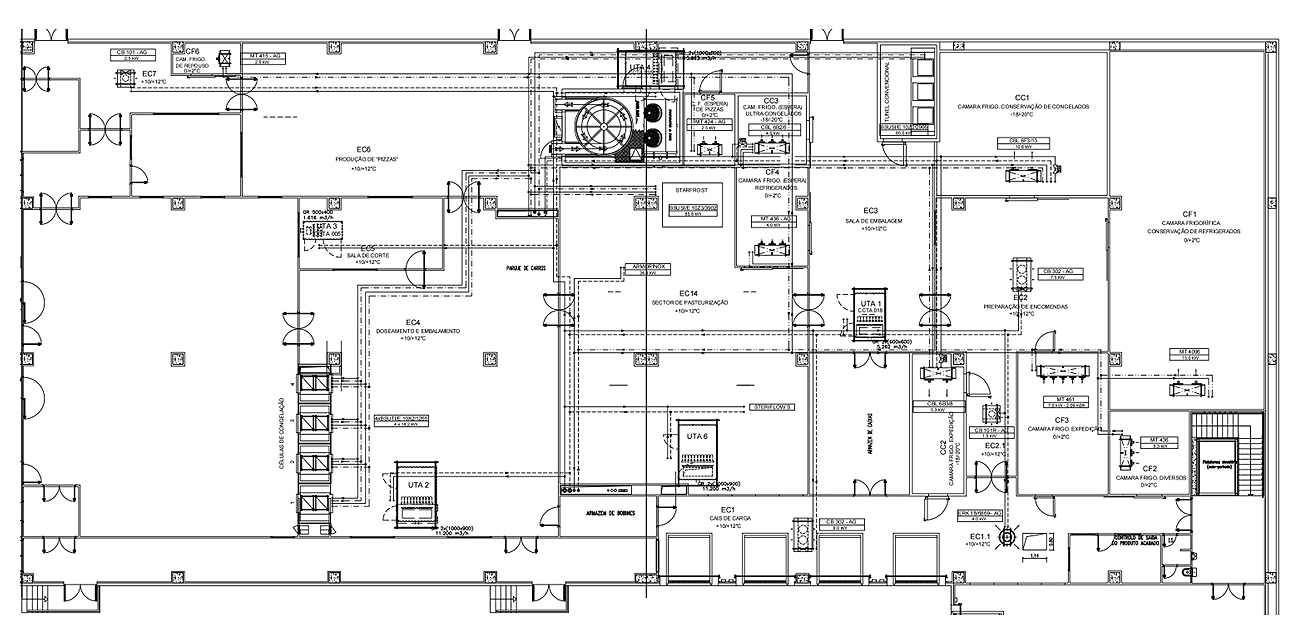 Figure 2. Installation layout (2/2). (Source: Dimensionar).
As previously mentioned, the original system of the case study (scenario 1) employs R404A and chilled glycol water, complemented by an ice bank, to serve multiple processes, including rapid cooling after pasteurisation, with a total refrigeration power of 964.3 kW. The original installation (scenario 1) is made up of six tunnels with different cooling capacities depending on the application for which they are intended, operating completely independently, each with its own refrigeration circuit. The facility also has a system of six freezer chambers with three different temperature levels: the conservation chamber (CC1), dispatch chamber (CC2) and deep-frozen chamber (CC3) have an interior temperature of −18 °C, the meat chamber (CC4) −20 °C, and finally the fish chamber (CC5) and vegetable chamber (CC6) −25 °C. Both the freezing tunnels and these chambers use R404A refrigerant, characterised by a very high GWP and ODP. The facility also has a system of eighteen refrigerated chambers fed by glycol-water solution, which operate at a temperature of 0–2 °C and are responsible for refrigerating various types of products. There is also an ice bank which is powered by glycol-water solution, and this has the essential function of supplying ice water for cooling pasteurised foods, because this type of process requires a high refrigeration capacity over a short period of time, making an ice bank system particularly suitable for this application. In addition, the ice bank supplies chilled water to the building’s air conditioning system, serving the cooling batteries of six Air Handling Units (AHUs) and eleven fan coils. The frozen food chambers are supplied by independent R404A systems.
In Figure 3 a schematic of the principle type of one of the freezing chambers is presented, while Figure 4 shows the Mollier diagram (R404A) of the freezing chamber circuit, with the different temperature levels and Figure 5 shows the overall principle diagram of the original installation, and Table 2. Shows the thermodynamic properties at the characteristic points of the original R404A system.
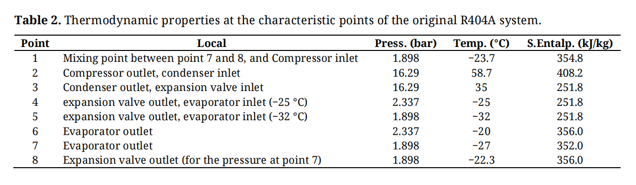 Table 2. Thermodynamic properties at the characteristic points of the original R404A system.
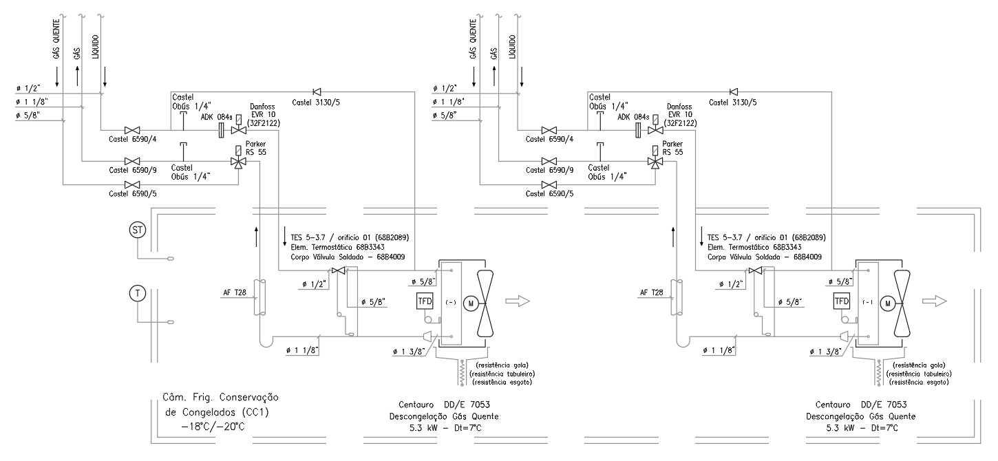 Figure 3. Schematic of the Freezer Room Type Principle for original system. (Source: Dimensionar).
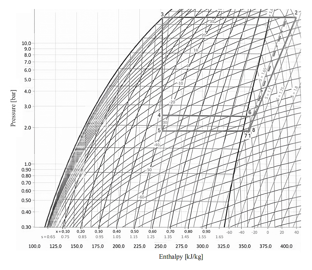 Figure 4. Mollier diagram of the freezing chambers for original system. (Source: Dimensionar).
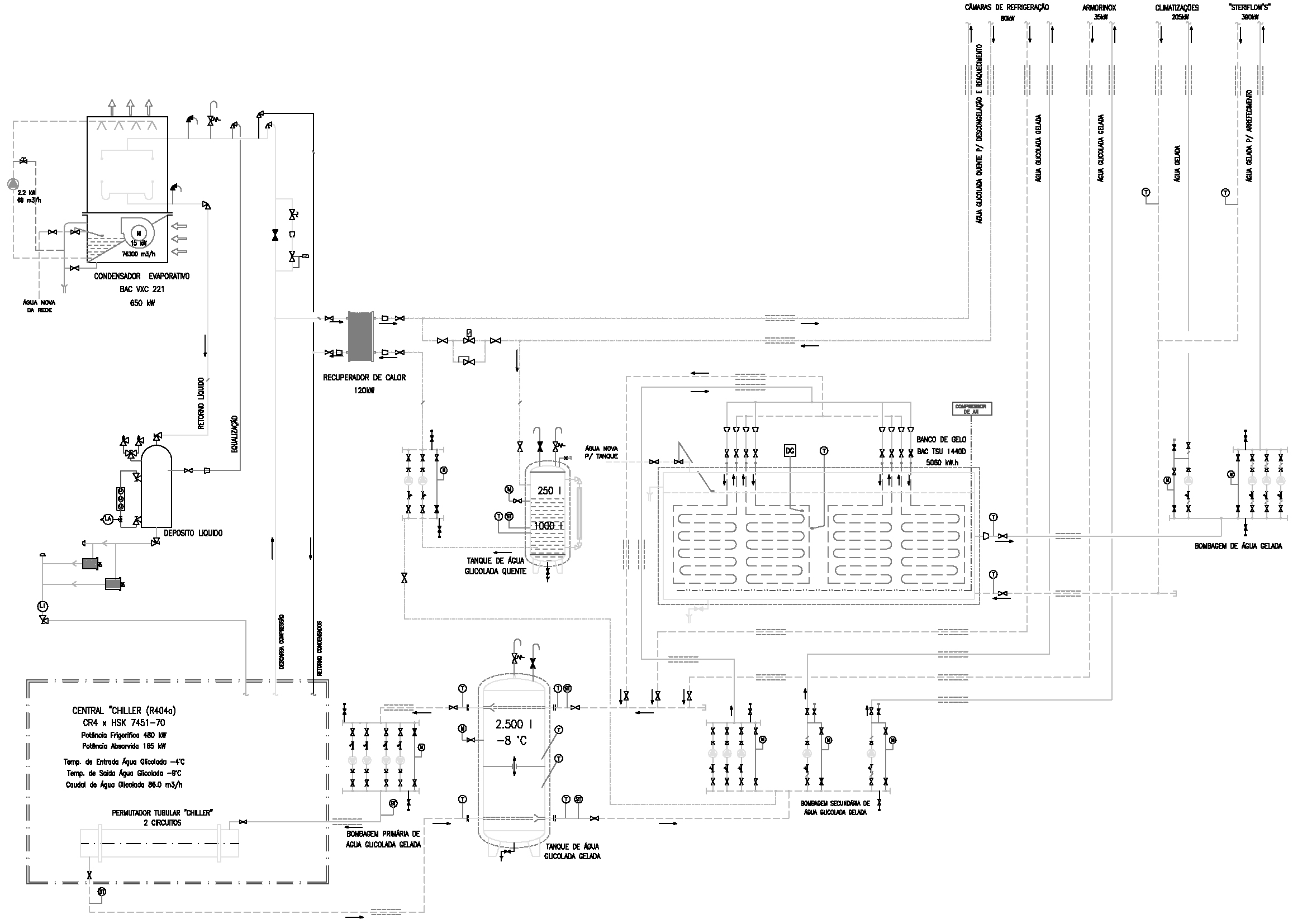 Figure 5. Overall principle diagram for original systems (Source: Dimensionar).
The proposed optimisation solution aims to improve the energy efficiency and sustainability of the original refrigeration installation. The main objective was to increase the COP (Coefficient of Performance) and reduce CO2 emissions, since optimising the system essentially involves improving overall efficiency. This can be achieved by choosing more efficient components and optimising the installation. Another key point is the replacement of the fluorinated refrigerant, R404A, with more sustainable alternatives such as ammonia (R717) and carbon dioxide (R744). This change is in line with environmental regulations and significantly reduces the ecological impact of the installation, thereby ensuring greater compatibility with current trends in the refrigeration industry. In addition to improving the refrigerants, all of the installation’s independent systems have been centralised. This approach increases energy efficiency by reducing the number of compressors and optimises thermal load control. In addition, centralisation reduces operating and maintenance costs, since a centralised system requires fewer redundant components and allows for more effective monitoring. A cascade system was chosen, in which ammonia (NH3) will operate at high pressure and carbon dioxide (CO2) at low pressure. This choice was made due to technical and safety factors, ensuring a more efficient and reliable system. As for the distribution of the circuits, it was decided that the CO2 circuit would be used to feed the freezing tunnels, freezing chambers and refrigeration chambers. The NH3 circuit will be used to feed the ice bank and, via a heat exchanger, to condense the CO2 circuit, thus reducing the condensation temperature. In addition, the NH3 circuit will also supply heat to the reheating system and the chamber defrosting process. This heat is recovered in an exchanger located at the outlet of the compressor, where the fluid temperature is higher. This allows energy to be utilised, since this heat would otherwise be dissipated into the environment, and it is reused at no additional cost, apart from the power absorbed by the circulation pumps. This defrosting circuit works with glycol-water solution, a choice based on two main reasons. The first is that the original installation already uses this fluid, thus avoiding additional costs and allowing it to be reused. The second reason is more technical: during the defrosting process, water passes through the evaporators, but when it stops, some of that water will remain inside. If pure water were used, without the presence of glycol, it would freeze inside the tubes due to the low surrounding temperature, which would lead to damage to the pipework. By using glycol-water solution, whose freezing temperature is significantly lower, this risk is reduced.
Power Balance–Optimised Installation (Scenario 2)As the optimised installation uses a cascade system, in which ammonia (NH3) will operate at high pressure and carbon dioxide (CO2) at low pressure, for this change it was necessary to regroup the refrigeration powers to be supplied by the two systems (NH3 and CO2). Table 3 shows the sums of the cooling powers of the optimised installation (scenario 2) for these two circuits and Figure 6 shows the principle diagram of the CO2 circuit.
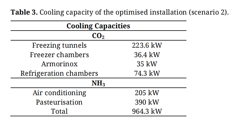 Table 3. Cooling capacity of the optimised installation (scenario 2).
In this system, CO2 is condensed in a plate exchanger, exchanging heat with the NH3 circuit. For the correct operation of the installation, four different temperature levels are envisaged: 0–2 °C for the refrigeration and Armorinox chambers, −18 °C and −25 °C for the frozen food chambers, and −35°C for the freezing tunnels, so the evaporation temperatures will be −5 °C, −25 °C and −32 °C, −40 °C, respectively. A liquid separator has been incorporated at the outlet of the CO2/NH3 exchanger, the main function of which is to ensure that only saturated liquid is fed to the evaporators of the refrigeration chambers, allowing operation in a flooded evaporator regime. If there is a gas/liquid mixture at the entrance to the separator, the gas, because it has a lower density, accumulates at the top of the separator and is led back to the exchanger along with the gas returning from the evaporators. It is important to emphasise that in order to avoid the need to compress this gas in order to move it to the exchanger, the liquid separator should be installed at a lower level than the plate exchanger, ensuring that the gas rises by natural convection to the exchanger due to the difference in height. With regard to frozen food chambers, given that the refrigeration power required is relatively low compared to freezing tunnels and refrigeration chambers, a direct expansion system was chosen. In this scenario, an expansion valve regulates the expansion of the fluid before it enters each evaporator, adjusting according to the desired temperature inside the chamber. Subsequently, a pressure regulating valve was installed, which equalises the fluid pressure after the evaporators to the pressure corresponding to the −32 °C chambers, allowing the fluid from different thermal levels to unify at a common pressure. The fluid then goes to a compressor which raises this pressure to the condensing pressure. An oil separator has also been incorporated at the outlet of the compressor to capture and separate any oil droplets present in the fluid, ensuring that it returns to the compressor and avoiding efficiency losses in the cycle. It is essential to guarantee adequate drainage and return of the oil to avoid accumulation in the exchangers, which could jeopardise thermal exchange. As far as the freezing tunnels are concerned, due to the high refrigeration power required, a liquid separator has once again been included to maximise efficiency. At the inlet of this separator is an expansion valve, responsible for reducing the fluid pressure to allow the storage of saturated liquid CO2 at a temperature of −40 °C. This solution allows the evaporator to operate on a flooded basis, substantially increasing the refrigeration effect, since the fluid enters the evaporator in a saturated liquid state, unlike what would happen in a direct expansion system, where a two-phase mixture would reduce the refrigeration effect. It was realised that there were no models suitable for operating at suction temperatures of −40 °C. To overcome this restriction, it was necessary to implement a heat exchanger before the compressor inlet, using as a secondary fluid the fluid coming from the liquid separator at −5 °C, which will then enter the separator at −40 °C after being expanded. This solution makes it possible to preheat the suctioned gas, raising its temperature by 5 °C, which means that the effective suction temperature of the compressor will be −35 °C. This increase opens up the possibility of choosing from a greater variety of compressors available on the market that are compatible with this operating range, making sizing easier. In addition to this technical advantage, the implementation of the exchanger also brings benefits in terms of the fluid entering the liquid separator at −40 °C. By giving up part of its thermal energy in the exchanger, the enthalpy of the fluid decreases, which means that, after undergoing expansion, the fluid enters the separator with a lower vapour title (i.e., lower vapour fraction). This effect contributes to better utilisation of the flooded evaporator regime, ensuring that a greater proportion of the fluid is in the liquid phase. After passing through the evaporator, the fluid returns to the liquid separator in the form of a gas-liquid mixture. The gas is then sucked through the upper part of the separator, passing through the heat exchanger before being directed to the compressor. In the compressor, the gas pressure is raised until it reaches condensing pressure. An isentropic efficiency of 85% was assumed for the compressors, representing typical values for modern industrial refrigeration equipment. In addition, a temperature difference of 5 °C was considered in the cascade heat exchanger between the condensing CO2 circuit and the evaporating NH3 circuit. Figure 7 shows the evolution of the Mollier diagram for the refrigerant R744 for this optimised solution (scenario 2) and Figure 8 shows the Principle Diagram of the R744 circuit for the optimised solution, with the marking of the enthalpic points (scenario 2). Table 4 shows the thermodynamic properties at the characteristic points of the R744 circuit optimised solution.
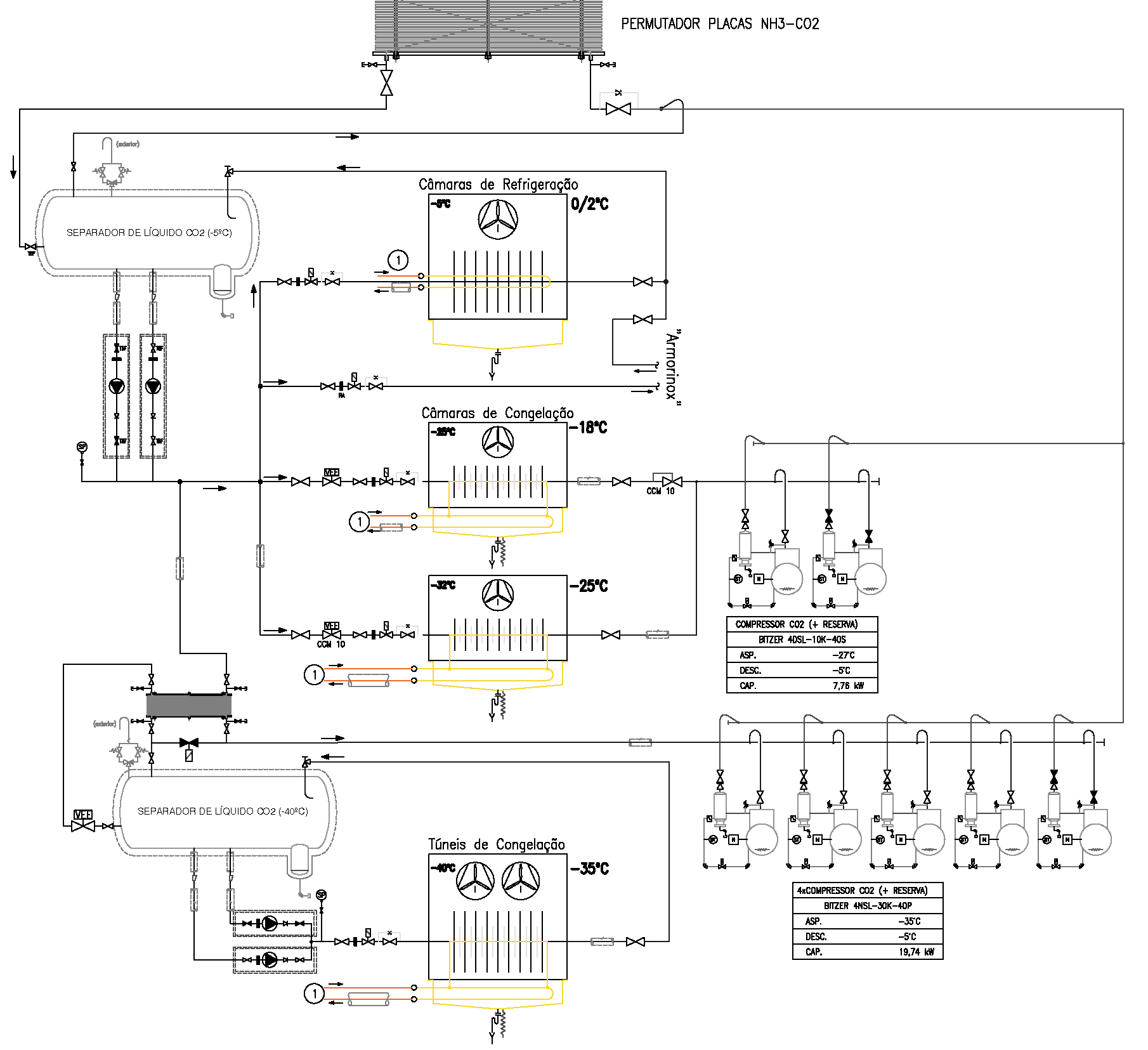 Figure 6. Principle diagram of the CO2 circuit (R744) optimised solution. (Source: Authors’ elaboration).
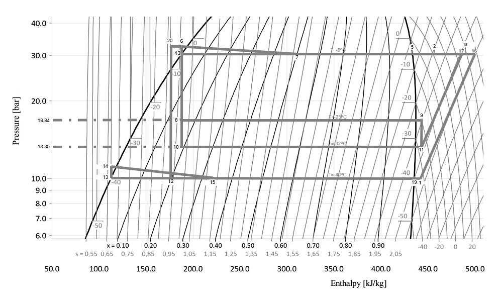 Figure 7. Mollier diagram–R744 circuit optimised solution. (Source: Authors’ elaboration).
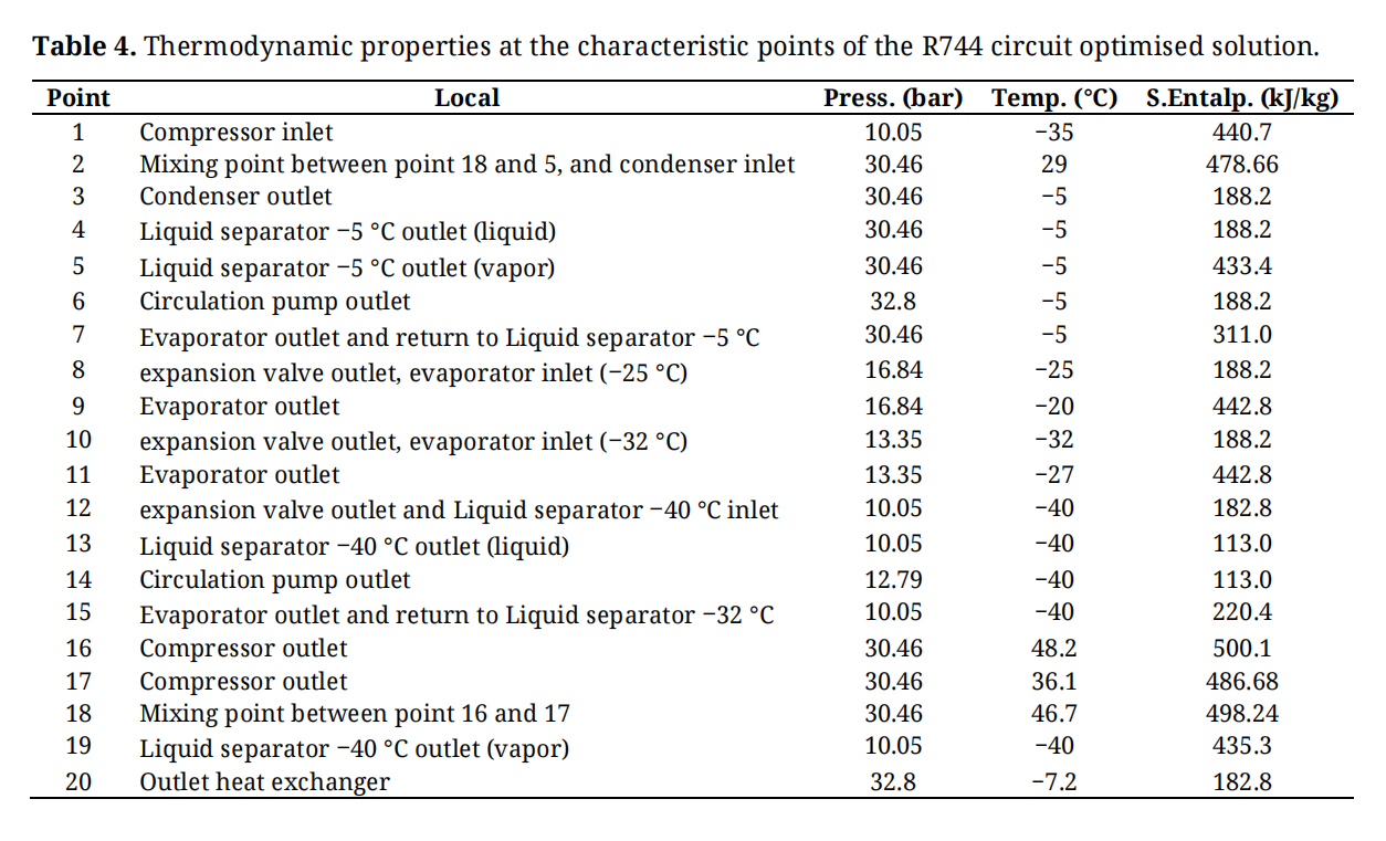 Table 4. Thermodynamic properties at the characteristic points of the R744 circuit optimised solution.
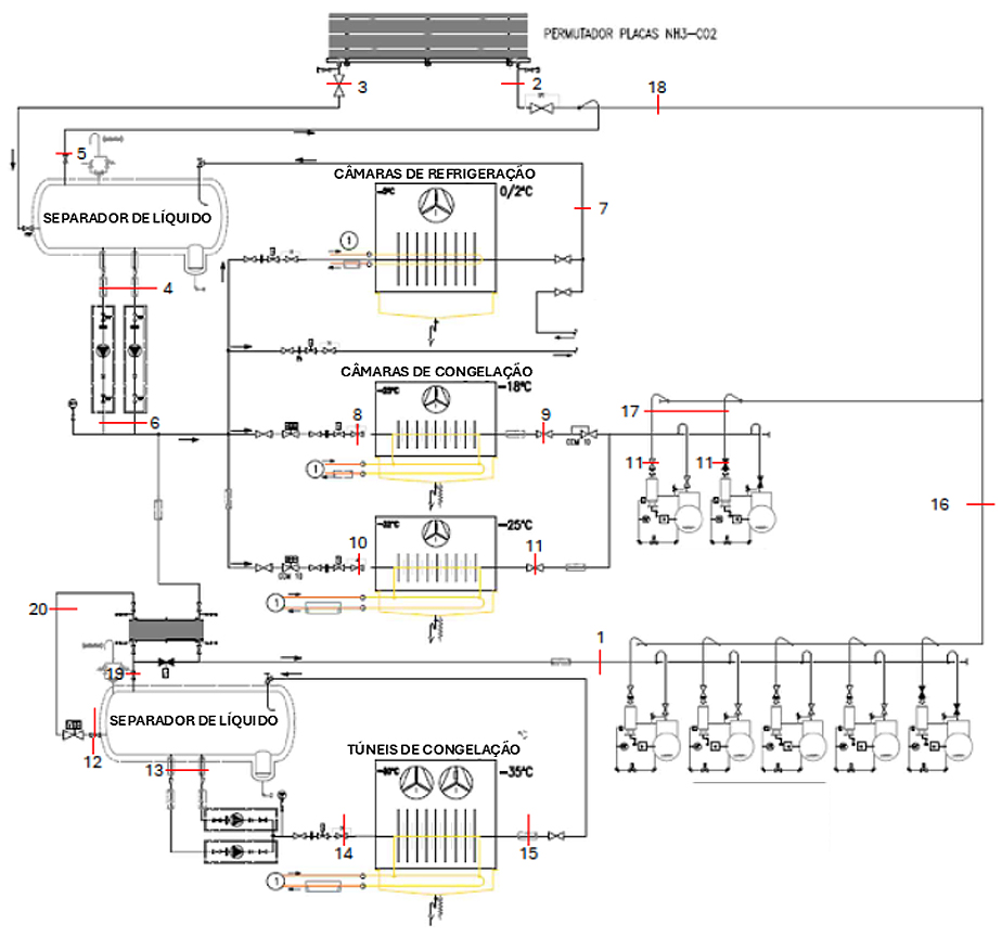 Figure 8. Principle diagram of the R744 circuit for the optimised solution (Source: Authors’ elaboration).
Figure 9 shows the principle diagram of the NH3 circuit for the optimised solution (scenario 2), where it can be seen that one of the first assumptions defined for this optimised solution was the continued use of a closed system with glycol-water solution for reheating and defrosting the chambers and tunnels. To this end, the ideal place to put the heat exchanger to transfer heat from NH3 to water more efficiently would be at the compressor discharge, where temperatures are highest. This location offers an additional advantage, as it reduces the temperature of the fluid at the inlet to the condenser, making it unnecessary to have such a powerful condenser. However, one of the main challenges of this application would be too high a temperature at the discharge. Since NH3 refrigeration systems operating at low evaporation temperatures may be subject to relatively high compression ratios, the compressor discharge temperature can become significantly elevated. For example, assuming a condensing temperature of 35 °C, discharge temperatures may easily exceed 110 °C due to the thermodynamic properties of ammonia and the associated temperature lift across the compressor., which would represent a significant risk for the glycol-water solution circuit and could lead to its evaporation. The solution found to this problem was to use a screw-type compressor. This type of equipment requires a large quantity of oil for its operation, lubrication and sealing. This amount of oil is responsible for absorbing a large amount of heat, thus limiting the discharge temperature to around 80 °C, the discharge temperature typically used for this type of compressor. This solution creates another problem, the need to cool the oil efficiently, since the ideal point for the oil to enter the compressor is 40 °C, according to compressor manufacturer Bitzer. Therefore, an efficient mechanism had to be found to cool the oil and, after analysing various options, the choice was made to use a thermosiphon. This mechanism has the advantage of not involving additional energy consumption, as it works by gravity and density differences. Its working principle consists of a reservoir containing saturated liquid from the condenser at 35 °C. From this reservoir, a lower line takes the liquid to a cross-flow exchanger located at a lower level, where heat is exchanged with the hot oil. In this exchanger the oil is cooled by the fluid, while the fluid will evaporate due to heat absorption. The vapour, which has a lower density, naturally rises to the top of the thermosiphon. In the thermosiphon, this vapour returns to the condenser through an upper connection point, and since the condenser is higher, there is no need for auxiliary circulation equipment. Also in the thermosiphon is the liquid separator, where there is an expansion valve at the inlet, which reduces the fluid pressure until it reaches a temperature of −8 °C. This liquid separator is used to distribute the fluid to the ice bank and to the NH3/CO2 plate exchanger, while the vapour is sucked in at the top to go back to the compressor. A temperature of −8 °C was assumed in the liquid separator, as this is an appropriate value to guarantee efficient condensation of the CO2 in the plate exchanger. In addition, this temperature is also advantageous for the operation of the ice bank, ensuring a good balance between the system’s energy efficiency and cooling needs. There is also an oil separator after the compressor which separates the fluid from the oil. Since the oil is denser, it accumulates at the bottom of the separator, this hot oil is then sucked up by a pump and then passes through the exchanger to cool down and return to the compressor. Figure 10 shows the evolution of the Mollier diagram for the refrigerant R717 for this optimised solution (scenario 2). Table 5 shows the thermodynamic properties at the characteristic points of the of NH3 circuit (R717) optimised solution.
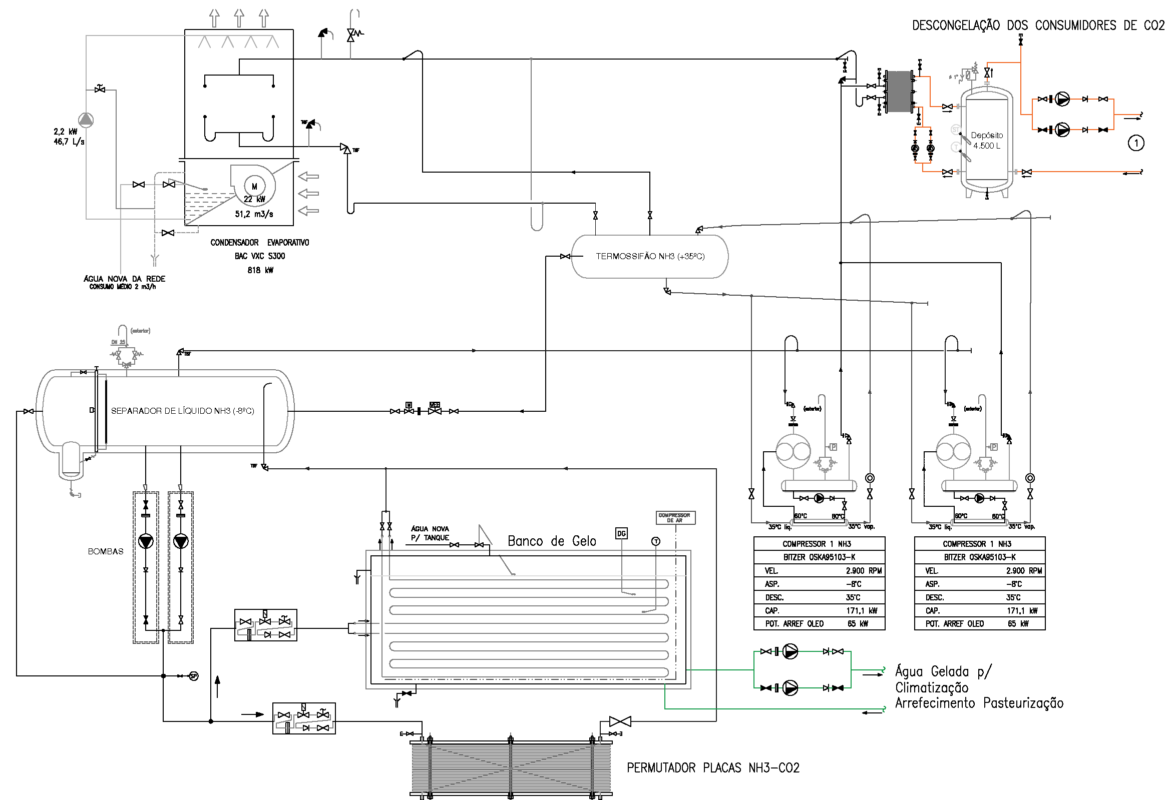 Figure 9. Principle diagram of the NH3 circuit for the optimised solution (Source: Authors’ elaboration).
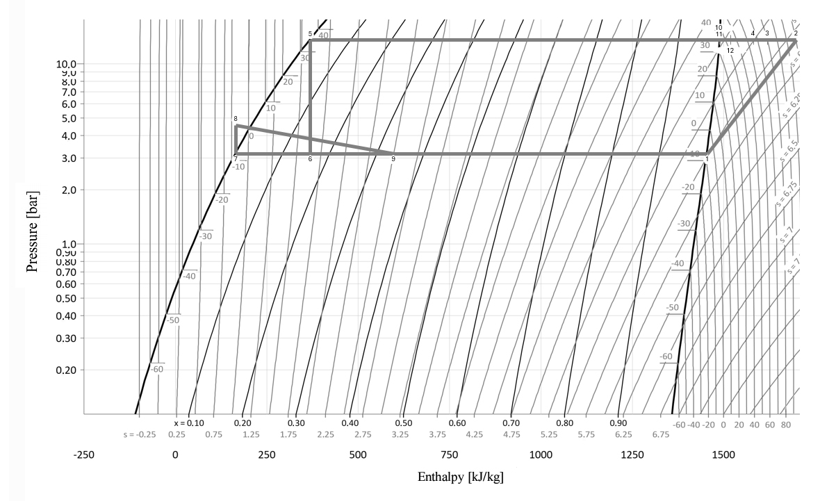 Figure 10. Mollier diagram–NH3 circuit (R717) optimised solution. (Source: Authors’ elaboration).
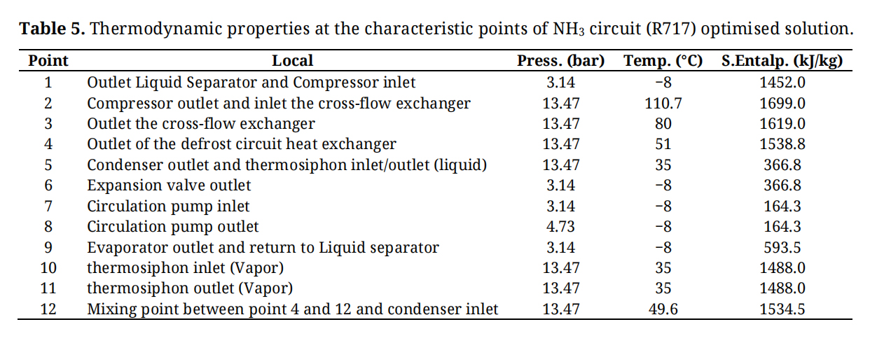 Table 5. Thermodynamic properties at the characteristic points of NH3 circuit (R717) optimised solution.
This section presents the comparative analysis between the original refrigeration installation (scenario 1) and the optimised installation (scenario 2), with the aim of comprehensively assessing the gains obtained from the measures implemented. Various parameters were taken into account in this assessment. Firstly, the absorbed electrical power was analysed as an indicator of the instantaneous electrical demand of the refrigeration system. Together with the refrigeration capacity, this parameter allows the calculation of the Coefficient of Performance (COP), which relates the refrigeration power produced to the electrical power consumed and provides a measure of the system’s energy efficiency. Next, the annual CO2 emissions resulting from electricity consumption were assessed, as well as refrigerant leaks, which are responsible for direct greenhouse gas emissions. These two factors are then integrated into the TEWI (Total Equivalent Warming Impact) index, which combines direct and indirect emissions over the useful life of the installation, constituting a global metric of the associated environmental impact. Finally, electricity costs were also analysed, both from an annual perspective and over the lifetime of the system, in order to quantify the economic impact of electricity consumption. The combined analysis of these indicators enables a clear comparison between the original situation and the optimised one, making it possible to assess not only the improvements in energy efficiency, but also the reduction in environmental impacts and the economic benefits associated with the optimisation measures. To ensure a consistent comparison between the original and optimised configurations, the refrigeration load was maintained unchanged in both scenarios. The annual operating schedule was established according to the operating characteristics of the installation, considering continuous operation throughout the year. Refrigerant leakage rates were selected based on commonly adopted industrial practice and the specific detectability characteristics of the refrigerants used. Indirect CO2 emissions were calculated using the official emission factor for the Portuguese electricity grid, ensuring consistency with the geographical context of the case study.
One of the methods for comparing systems is by calculating the COP (Coefficient of Performance). This coefficient represents the relationship between the cooling capacity (amount of heat removed per unit of time), i.e., the desired output of the installation, and the electrical power consumed by compressors or pumps, i.e., the costs of running the installation. The COP calculation is given by (1) [11]:
where:
Refrigeration Power: Cooling capacity of the system (kW);
Absorbed Electric Power: Electric power that the system needs to be driven (kW).
The higher the COP, the more efficient the system, since this means that for the same heat removal from the desired space, it will consume less energy.
CO2 EmissionsCarbon dioxide (CO2) emissions are one of the main environmental indicators used to quantify the impact of industrial activities on global warming. Growing regulatory pressure reinforces the need to monitor and reduce emissions associated with production processes. In the industrial refrigeration sector, the relevance of this analysis is particularly significant, given the high energy consumption. Calculating CO2 emissions involves calculating the indirect emissions associated with the refrigeration system, i.e., total emissions without taking into account direct emissions that occur directly in the installation, such as leaks. Equation (2) was used for this purpose [11]:
where:
n : Installation lifetime (years);
E : Annual energy consumption of the equipment
FE : Electricity CO2 Emission Factor
For this purpose, it was assumed that in the original installation is designed to operate for 20 years and with a CO2 emission factor from electricity of 0.159 kgCO2/kWh, value referring to mainland Portugal, in the year 2022 [23]. For the optimized installation the number of operating hours, the value used for the NH3 circuit was assumed, i.e., 20 h per day. For the number of days of operation, it has been assumed that the installation will operate throughout the year, i.e., 365 days. The indirect CO2 emissions associated with electricity consumption were calculated using the official emission factor for the Portuguese electricity grid. Consequently, the reported emission values are representative of the geographical and temporal context considered in this study and may vary for different electricity generation mixes or future grid decarbonisation scenarios.
TEWI IndexCalculating the TEWI index involves adding up the direct and indirect emissions associated with the refrigeration system. Equation (3) was used for this purpose [11]:
where:
GWP : Global Warming Potential of Refrigeration Fluid;
L : Annual Refrigerant Fluid Loss
n : Installation lifetime (years);
E : Annual Energy Consumption of the Systems
FE : Electricity CO2 Emission Factor
Again, it was assumed that the installation for both cases is designed to operate for 20 years and that the CO2 emission factor for electricity is 0.159 kgCO2/kWh [24]. With regard to refrigerant losses, these figures can vary significantly depending on various factors, such as the type of installation, the frequency and quality of maintenance carried out and the type of fluid used. As fluorinated refrigerants and carbon dioxide are odourless, their detection becomes more difficult, requiring the use of specific sensors. These sensors are generally only activated when the concentration of the fluid in the air is already high, which can lead to longer and larger leaks. For this reason, typically in industry, it is common to consider an annual loss rate of around 5% of the total volume of fluid in the installation. For ammonia, on the other hand, due to its intense and characteristic odour, the slightest leak is easily detectable, allowing for rapid intervention. Therefore, ammonia losses tend to be residual and can be considered negligible, or approximately 0%. To calculate leakage losses, the lengths of the pipes were quantified to obtain the total volume of fluid in the installation, based on the layout of the installation. And by applying the percentage of leakage defined above, the value of annual losses is obtained. In the case of the optimised installation, due to a lack of data, only the volumes of the two circuits (R744 and R717) were totalled.
The following data was considered for the original installation:
●
●
●
●
●
The following data was considered for the optimised installation:
●
●
●
●
●
●
●
●
●
It should be noted that the TEWI analysis performed in this study is limited to direct refrigerant emissions and indirect emissions associated with electricity consumption during system operation. Environmental impacts related to equipment manufacturing, transportation, installation, maintenance, and end-of-life disposal were not considered. Therefore, the results represent the operational environmental performance of the refrigeration system rather than a complete lifecycle assessment. Future work may incorporate a full Life Cycle Assessment (LCA) to provide a more comprehensive evaluation of the environmental impacts associated with the proposed retrofit strategy. The TEWI calculations were performed using representative design values for refrigerant charge and leakage rates. Although these assumptions are consistent with values commonly reported in the literature and industrial practice, uncertainties associated with these parameters may affect the absolute TEWI results. Future work should include sensitivity analyses to evaluate the influence of refrigerant charge, leakage rates, equipment lifetime, and electricity emission factors on the environmental performance assessment.
Energy CostsA comparative study of the installation’s annual electricity costs was carried out. For this purpose, it was assumed that the installation operates under an electricity supply contract structured into four different tariff periods: peak hours, full hours, normal off-peak hours and super off-peak hours. It was also assumed that the supply falls within the medium voltage level.
The following price values were obtained for each type of time slot [25]:
●
●
●
●
Averaging the values gives a figure of 0.01415 €/kWh, which was the value used for the calculation. It should be noted that the electricity cost calculation was intended to provide a comparative estimate of the operating costs associated with the two refrigeration configurations. Therefore, an average electricity tariff was adopted as a simplifying assumption. Since actual electricity costs depend on the operating schedules of the different refrigeration circuits and their distribution across the various tariff periods, the reported values should be interpreted as approximate comparative indicators rather than exact operating costs.
Comparative ResultsTable 6 shows the comparison between the original refrigeration installation and the optimised installation, highlighting the main energy performance parameters, environmental impact and operating costs.
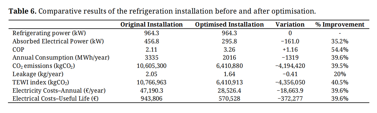 Table 6. Comparative results of the refrigeration installation before and after optimisation.
The cooling power was kept constant at 964.3 kW in both configurations, ensuring that any variations in the results obtained are exclusively related to the changes made to the installation and not to the change in cooling capacity. The absorbed electrical power values used in the comparison were obtained from the technical information of the equipment considered in each scenario. For both the original and optimised installations, the total absorbed electrical power includes all relevant electricity-consuming components of the refrigeration system, namely compressors, pumps, fans, and auxiliary equipment. Thus, the values reported represent the total installed absorbed electrical power associated with each configuration and were used, together with the refrigeration capacity, to calculate the corresponding COP values. The absorbed electrical power showed a significant reduction, going from 456.8 kW in the original installation to 295.8 kW in the optimised one, which represents a reduction in absorbed electrical power of 161 kW and a 35.2% improvement in energy consumption. This improvement is related to three main factors, the first being the use of more recent equipment, so it is to be expected that the efficiencies of the equipment will be higher than those used in the original installation. Another factor was the integration of all the independent systems into a single one, which led to a reduction in the number of compressors, pumps and condensers, as was the case with the tunnels and freezing chambers, which were independent systems in the original installation, and by adding them to the main system, it not only simplifies the installation, but also reduces the number of redundant pieces of equipment, thus reducing the electrical power absorbed. The use of different refrigerants also contributed to the improved performance of the system. In the proposed cascade configuration, CO2 (R744) was employed in the low-temperature stage, where its high volumetric refrigeration capacity is advantageous, while NH3 (R717) was used in the high-temperature stage due to its favourable thermodynamic efficiency and excellent heat transfer properties. The combination of these refrigerants in a cascade arrangement contributes to the overall improvement in system performance reported in this study. Thus, CO2 was applied in low temperature (low pressure) regimes, where it has high efficiency and excellent heat transfer capacity, while NH3 was used at high pressure levels, taking advantage of its high latent heat of evaporation and its critical point well above the critical point of CO2. This careful selection made it possible to optimise the overall operation of the installation and reduce electricity consumption. This reduction in absorbed electrical power is directly reflected in the increase in COP, which went from 2.11 to 3.26, corresponding to a 54.4% increase in system efficiency. This result shows that the optimised installation is able to provide the same cooling capacity with substantially lower electricity consumption, ensuring more economical and sustainable operation. From an environmental point of view, the annual consumption was first calculated taking into account the electrical power absorbed and the number of hours the installation operates each year, and an improvement of 39.6% was obtained. Next, there was a significant reduction in annual CO2 emissions, which fell from 10,605,300 kgCO2 to 6,410,880 kgCO2, representing a reduction of 39.5%. This improvement is directly related to the reduction in electrical power absorbed, i.e., the reduction in annual electrical consumption (which reduces indirect emissions). Although absorbed electrical power is presented as an indicator of system performance and efficiency improvement, the evaluation of energy savings was based on annual electricity consumption, which represents the most appropriate metric for assessing energy performance, operating costs, and indirect CO2 emissions. The significant improvement in COP observed in the optimized refrigeration system results from the combined effect of several thermodynamic and operational optimisation measures. One of the main factors is the implementation of a centralized cascade configuration using CO2 (R744) in the low-temperature stage and NH3 (R717) in the high-temperature stage. By dividing the refrigeration process into two temperature levels, the compression ratio required in each stage is reduced, decreasing compressor work and improving overall cycle efficiency. In addition, the cascade configuration allows a better thermal matching between the refrigeration demand and the operating conditions of each refrigerant. CO2 presents favourable characteristics for low-temperature applications due to its high volumetric refrigeration capacity, while NH3 provides high thermodynamic efficiency and excellent heat transfer properties in the high-temperature stage. The use of NH3 to condense the CO2 circuit through the cascade heat exchanger also contributes to lowering the effective condensation temperature of the low-temperature cycle, further improving system performance.
Another important contribution comes from the centralization of the previously independent refrigeration systems. This approach reduces the number of operating compressors, improves thermal load management, and allows a more stable and efficient operation under varying cooling demands. Furthermore, the optimized system incorporates heat recovery from the NH3 compressor discharge for chamber defrosting and reheating processes. This recovered thermal energy would otherwise be rejected to the environment, and its reuse contributes to improving the overall energy efficiency of the installation without significant additional energy consumption. Therefore, the observed COP improvement cannot be attributed to a single factor, but rather to the combined effect of refrigerant replacement, cascade system integration, reduction of compression work, improved thermal management, system centralization, and heat recovery strategies.
Another point of comparison was in relation to leaks in the installation, which fell from 2.05 kg/year to 1.64 kg/year. For this comparison, the total volume of the installation was first calculated and then, depending on the type of fluid, a percentage of annual losses was taken into account. This decrease is especially related to the NH3 circuit, since this fluid has a characteristic odour, is easily detectable at the slightest leak, and therefore leaks for this fluid were considered to be approximately 0%, unlike what happened in the original installation and the CO2 circuit, which was considered to be 5%. The combined impact of direct emissions (leaks) and indirect emissions (electricity consumption) is represented by the TEWI Index, which showed a reduction of 40.5%, from 10,766,963 kgCO2 to 6,410,913 kgCO2. This decrease shows that the measures implemented have a significant effect on mitigating the environmental impact over the lifetime of the installation. In economic terms, annual electricity costs fell from €47,190.3 to €28,526.4, corresponding to a saving of 39.6% per year. This improvement is again related to the reduction in annual electricity consumption, which when multiplied by the average electricity tariff gives the annual electricity costs. Projecting the annual electricity costs over the system’s lifetime, a cumulative saving of €372,277 was estimated, which reinforces the positive impact of optimisation not only on environmental performance, but also on the economic viability of the operation. In short, this analysis proves that the optimised installation shows significant gains in all the parameters assessed: greater energy efficiency, a significant reduction in greenhouse gas emissions and a significant reduction in operating costs.
It should be noted that the performance improvements obtained in the optimized scenario cannot be attributed exclusively to the replacement of the refrigerant. The proposed optimization simultaneously included the implementation of a centralized cascade architecture and the selection of new equipment adapted to the operating conditions of the system. Therefore, the reported gains result from the combined effect of refrigerant properties, system integration, and equipment modernization. Future work may focus on a parametric assessment of the individual contribution of each factor to the overall system performance.
Safety and Regulatory ConsiderationsAlthough the proposed NH3/CO2 cascade refrigeration system offers significant energy and environmental advantages, its implementation requires compliance with established refrigeration safety standards and regulations. Due to the toxicity and mild flammability of ammonia, the refrigerant should be confined to dedicated machinery rooms equipped with leak detection systems, mechanical ventilation, emergency shutdown procedures, and appropriate pressure relief devices. In addition, the refrigerant charge should be minimised whenever possible to reduce potential risks. The CO2 circuit, while environmentally benign, operates at significantly higher pressures and therefore requires suitable pressure-rated components, pressure relief systems, and appropriate control strategies. The design, installation, operation, and maintenance of the refrigeration system should comply with the requirements of EN 378 regarding installation site safety, ventilation, leak detection, and personnel protection [26], ISO 5149 for system design, construction, testing, and documentation requirements [27], and the Pressure Equipment Directive (PED 2014/68/EU) for pressure-containing equipment operating under elevated pressures [28]. Compliance with these standards ensures the safe and reliable operation of NH3/CO2 cascade refrigeration systems.
Comparison with Previous Studies and Practical ImplicationsPrevious studies on industrial refrigeration sustainability have predominantly focused on refrigerant substitution, component-level efficiency improvements, or the environmental assessment of alternative refrigerants. While these approaches have demonstrated important reductions in energy consumption and greenhouse gas emissions, they often address individual aspects of system performance. The optimisation strategy proposed in the present study adopts a more integrated approach by combining refrigerant replacement, system centralisation, and overall plant redesign within a single industrial refrigeration framework. Compared with conventional retrofit strategies based solely on replacing high-GWP refrigerants, the proposed NH3/CO2 cascade configuration offers additional benefits, including improved energy efficiency, reduced indirect emissions through lower electricity consumption, and enhanced environmental performance resulting from the use of natural refrigerants with negligible or zero global warming potential. Furthermore, the centralised architecture facilitates future implementation of heat recovery solutions, advanced control strategies, and integration with renewable energy systems. However, the proposed approach also presents some limitations. The system architecture is inherently more complex than conventional direct-expansion systems, requiring specialised design expertise, advanced control strategies, and additional safety measures associated with ammonia toxicity and the high operating pressures of CO2 systems. Moreover, the present study focuses on operational performance and TEWI reduction and does not include a full lifecycle assessment or a detailed investment-based economic analysis. Despite these limitations, the results demonstrate that the proposed integrated optimisation strategy represents a viable pathway for improving the sustainability and energy performance of industrial refrigeration installations.
This article consisted of the study and development of a proposal to optimise an existing refrigeration installation. The refrigerant R404A, which has a high environmental impact, was replaced by natural refrigerants with low or no impact, namely R744 and R717.
In addition to the change in fluids, the operating philosophy of the plant, which originally operated with several independent systems, was modified. One optimisation measure was to combine all these systems into one. It was also proposed to implement an NH3/CO2 cascade cycle, bringing together the benefits of both fluids, since CO2 works best at low temperatures and exchanging heat at a lower level than the ambient temperature. NH3, on the other hand, has a much higher critical point and is more suitable for exchanging heat with the environment. This choice took into account the specific characteristics of natural refrigerants, such as the pressure and temperature of the fluid. Liquid separators, circulation pumps, compressors, evaporators, exchangers and some accessories compatible with these requirements were selected.
The comparative analysis between the original system and the proposed solution revealed significant improvements in all the parameters analysed. The absorbed electrical power was reduced from 456.8 kW to 295.8 kW, corresponding to a saving of 35.2%. As a result, the Coefficient of Performance (COP) increased from 2.11 to 3.26, an improvement of 54.4%, which shows that the optimised installation produces the same cooling capacity with lower energy consumption.
In terms of environmental impact, annual CO2 emissions fell by around 39.5%, from 10,605,300 kgCO2 to 6,410,880 kgCO2. Refrigerant leaks were also reduced from 2.05 kg/year to 1.64 kg/year. This set of factors contributed to a 40.5% reduction in the TEWI Index, equivalent to 4,356,050 kgCO2 less over the lifetime of the installation. It is important to emphasise that this reduction is mainly attributable to lower electricity consumption from the grid and, consequently, to the reduction in indirect emissions, rather than to the replacement of HFCs with low-GWP natural refrigerants. Therefore, one measure that could be taken could be the implementation of renewable energies in the installation, such as the use of photovoltaic panels or wind turbines. This would reduce the need to use the public grid, and in turn reduce indirect emissions.
In terms of economic aspects, annual electricity costs fell from €47,190.3 to €28,526.4, representing an annual saving of 39.6%. Over the expected useful life of the installation, this corresponds to accumulated savings of €372,277. Results validate the adopted strategy, demonstrating that significant improvements in the performance and sustainability of refrigeration systems can be achieved without compromising cooling capacity. However, it should be noted that the reported improvements result from the combined effect of several modifications implemented in the optimized scenario, including the replacement of R404A with natural refrigerants (R744/R717), the transition from independent systems to a centralized cascade configuration, and the modernization and reselection of equipment adapted to the new operating conditions. Therefore, the observed gains in COP, energy consumption, and environmental performance cannot be attributed exclusively to the refrigerant substitution itself.
The results obtained in this study are consistent with recent research on natural refrigerants and NH3/CO2 cascade refrigeration systems. Several authors have reported that the adoption of natural refrigerants, combined with optimized system architectures and heat recovery strategies, can significantly improve energy efficiency while reducing environmental impacts and supporting long-term sustainability objectives. Recent studies have also highlighted the potential of cascade refrigeration systems to achieve lower energy consumption, improved thermodynamic performance, and enhanced environmental performance in industrial refrigeration applications. These findings further support the suitability of NH3/CO2 cascade technology as a promising solution for the transition towards more sustainable refrigeration systems [29–35].
Future work should focus on extending the proposed optimisation through both technical and operational enhancements. A detailed dynamic simulation of the NH3/CO2 cascade system under varying load conditions and ambient temperatures would allow a more accurate assessment of its seasonal performance and part-load behaviour. Experimental validation through pilot-scale or real-installation monitoring would also be valuable to confirm the theoretical results and identify potential operational challenges, such as control strategies, safety management, and maintenance requirements associated with natural refrigerants. Furthermore, future studies should aim to quantify the individual contribution of each optimisation factor, namely refrigerant replacement, system centralization, and equipment modernization, in order to better understand their respective impacts on system efficiency and sustainability performance. In addition, the integration of renewable energy sources, such as photovoltaic or wind systems, should be analysed in detail to further reduce indirect emissions and operating costs, including an evaluation of energy storage solutions to match cooling demand. Finally, a more comprehensive economic analysis considering investment costs, payback period, and sensitivity to electricity prices and carbon taxation would strengthen the assessment of the long-term feasibility and scalability of the proposed solution.
As this study evaluates the optimisation of an existing industrial refrigeration installation rather than the implementation of a new system, economic indicators such as payback period and Net Present Value (NPV) were not calculated. These indicators require a clearly defined investment baseline and comparable capital expenditures, which are not available for the original installation. Therefore, the economic assessment was limited to operating cost savings, while a more detailed techno-economic analysis is proposed also for future work.
The dataset of the study is available from the authors upon reasonable request.
Conceptualization, JG and GB; methodology, JG and GB; software, GB; validation, JG and GB; formal analysis, JG and GB; investigation, GB; resources, JG; data curation, JG and GB writing—original draft preparation, GB; writing—review and editing, JG; visualization, JG; supervision, JG; project administration, JG; funding acquisition, JG. All authors have read and agreed to the published version of the manuscript.
The authors declare no conflict of interest.
This research received no external funding.
The authors acknowledge the colleagues, collaborators, and staff of Dimensionar for providing indirect support during this study, including administrative assistance and technical guidance. These contributions facilitated the research but are not reflected in the author contributions or funding statements. The authors also gratefully acknowledge Eng. Carlos Duque for his continuous support.
1.
2.
3.
4.
5.
6.
7.
8.
9.
10.
11.
12.
13.
14.
15.
16.
17.
18.
19.
20.
21.
22.
23.
24.
25.
26.
27.
28.
29.
30.
31.
32.
33.
34.
35.
Barroso G, Garcia J. Advancing Sustainable Industrial Refrigeration: Energy, Environmental and Operational Cost Assessment of a CO2–NH3 Cascade System in Portugal—A Case Study. J Sustain Res. 2026;8(3):e260066. https://doi.org/10.20900/jsr20260066.

Copyright © Hapres Co., Ltd. Privacy Policy | Terms and Conditions


